What Materials Are Commonly Used in the Construction of Rigid Flex PCBs?
Construction of Rigid Flex PCBs
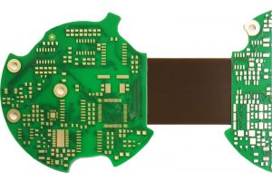
Rigid flex circuit boards combine rigid and flexible sections to offer the best of both worlds. This combination makes them an attractive solution for a wide variety of applications in sectors like industrial automation, automotive electronics, consumer devices, and medical technology. They offer improved electromechanical functionality, such as dynamic bending and vibration resistance, in addition to weight reduction, space savings, and superior thermal management.
Rigid Flex PCBs are fabricated using a similar process as standard rigid flex board, but include several key differences. The most important is the layer structure, which includes both rigid and flexible layers extending to each edge of the board. To ensure proper function, these layers must be precisely aligned and bonded together during the assembly process. The precise alignment is achieved through advanced manufacturing techniques that employ optical registration systems and laser drilling. These technologies also make it possible to create transition areas between rigid and flexible sections without compromising the integrity of either section.
The flex and rigid sections are typically made of different materials to achieve the required flexibility and mechanical performance. Rigid sections typically consist of FR-4 or other MDF-style materials, while flex sections are usually constructed from more flexible polyimide (PI) foils. The choice of material depends on the underlying copper conductor, flexibility specifications, and cost requirements of the design.
What Materials Are Commonly Used in the Construction of Rigid Flex PCBs?
Both flex and rigid sections must be adhered to the rigid board using durable adhesives that can withstand elevated temperatures and fluctuating humidity. The adhesives must also be capable of withstanding the dynamic flexing required of the circuit. To meet these needs, the adhesives used for rigid flex PCBs are often epoxy-based, but they can also be acrylic or polyimide-based.
In the construction of rigid flex circuits, it’s important to carefully plan the placement of the rigid and flexible sections to minimize stress concentrations and signal degradation. For this reason, the design phase of a rigid flex circuit requires an intimate knowledge of bending and mechanical performance. This is accomplished through FEA and rigorous testing, which are used to optimize the structural integrity of the board to ensure that it can withstand the intended operational environment.
Once the layers of the rigid flex circuit are properly aligned and bonded, they can be drilled and plated with copper. A solder mask is then applied to protect the copper traces from corrosion and oxidation. The final product is a fully functional rigid-flex circuit board that can eliminate the need for a wire harness in its enclosure, saving valuable production time and costs.
To avoid connectivity issues, it’s vital to design a rigid-flex circuit with an appropriate copper thickness, avoiding thin spots where the conductive pathways are exposed and too close to the edges of the board. It’s also important to keep flex areas free of discontinuities like cutouts, slits, and holes, as these can lead to stresses that compromise the performance of the circuit. Finally, it’s important to keep the drill-to-copper distance as large as possible, so that flex sections don’t experience premature fatigue and failure.